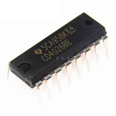
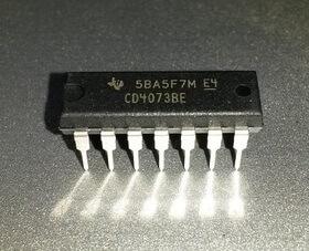
CD4026 is the equivalent of CD4543, IC4033, IC4511.
Where to use CD4026 IC?
The IC CD4026 is an IC which can perform the function of both a counter as well a 7-segment Driver. One single IC can be used to count form zero (0) to nine (9) directly on a Common Cathode type 7-segment display. The count can be increased by simply giving a high clock pulse; also more than one digit (0-9) can be created by cascading more than one CD4026 IC. So if you have a 7-segment (CC) display on which you have to display numbers that are being counted based on some condition then this IC will be a perfect choice.
How to use a CD4026 IC?
The IC can work from 3V to 15V, but normally powered with +5V to the Vdd/Vcc pin and the Ground/Vss pin is connected to ground. We have 7 output pins naming from Out A to Out G which is directly connected to the 7-segment display. The clock inhibit pin (pin 2) has to be held low (ground/0V) so that the clock signals can be sent to the IC also the Enable Input pin (pin 3) should be made high (+5V) so that the output pins (Out A to G) can be made active.
The 7-segment pins will increment the count by one number each time when the clock pin (pin 1) is made high. This clock source can either be obtained from a 555 IC or any other digital IC which is TTL compatible. They simply have to generate a pulse of low voltage 0V and high voltage 5V. In the circuit below I have used a clock source of 1Hz to increment the count. So the number will get incremented for every (T=1/F) 1 second.
The Reset pin (pin 15) is used to reset the count back to zero when made high. There are three other output pins (pin 5,4,14) which will be used only when the IC needs to be cascaded. The pin Carry over (CO – pin 5) will stay high by default, but when the count reaches “9” it will give a small pulse and count will continue from “0” again. This small pulse can be used to drive the clock pin of a cascaded IC to display more than one digit. The Direct Enable output (DEO) pin will always stay high, to enable any cascaded IC, if available. The Ungated C segment pin (pin 14) is used for any division operation; this pin will stay high by default and will go low when the count reaches “2”.
https://components101.com/ic-cd4026-pinout-circuit-datasheet

